skip to Main Content
Global buyers evaluating China’s leading hydraulic valve manufacturers face a practical challenge: comparing performance across very different applications. A valve controlling a compact excavator should not be judged by the same criteria as one serving a steel mill. Pressure, flow capacity, response time, contamination tolerance, and service access all matter.
Grand View Research estimated the global hydraulic equipment market at USD 39.2 billion in 2023 and projected continued growth through 2030. This figure covers hydraulic equipment broadly, not hydraulic valves alone. It still signals the scale of investment behind fluid-power systems—and the importance of verifying supplier claims against documented specifications. Ask for test data, material details, production traceability, and evidence of consistent quality. A polished catalog is not enough.
Fluid-power researcher John Watton’s work on control systems points to an important buying principle: valve performance depends on how the component behaves within the complete circuit, not just on its headline pressure rating. That distinction can be easy to miss. A small mismatch in spool response or contamination control may become visible only after installation, when downtime is expensive. This guide examines Chinese manufacturers through product range, engineering support, certification, customization, and export experience. It also recognizes a limitation: supplier information may be incomplete or difficult to compare. Careful buyers should validate critical claims directly before committing.
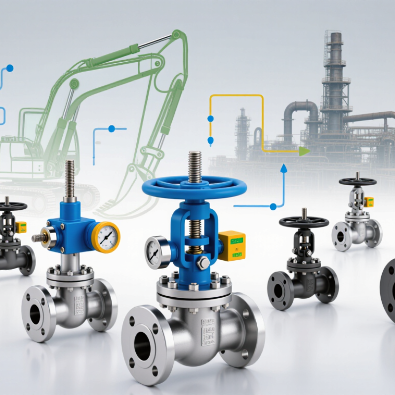
ISO 1219 gives hydraulic drawings a shared visual language. Its two parts cover graphical symbols and circuit diagrams: ISO 1219-1:2012 defines symbols, while ISO 1219-2:2012 explains diagram presentation. This distinction helps global buyers compare specifications across suppliers. A symbol describes a valve’s function, not its internal design or brand.
Directional control valves use adjoining squares to show positions. Arrows and blocked ends indicate flow paths; a spring or solenoid symbol shows how the valve shifts. Check valves allow flow in one direction, while pressure-control and flow-control symbols identify different circuit functions. Read each symbol with its port labels and operating conditions. A small detail matters: the same valve function can be built with different internal structures.
Tip: Check the symbol against the ISO 1219 reference, then confirm port sizes, pressure ratings, and control method in the datasheet. A tidy diagram can still hide an unclear specification. That is easy to overlook. ISO provides the drawing convention, but it does not verify a product’s performance. Ask for test data when operating limits matter.
Global buyers comparing Chinese hydraulic valve manufacturers should look beyond headline catalog figures. Rated pressure needs context: ask whether it applies to continuous operation, intermittent duty, or a brief peak. A valve rated at 315 bar may not suit a circuit that repeatedly approaches that limit. Details matter. Request test conditions, fluid temperature, and leakage limits alongside the pressure rating.
Flow capacity is equally practical. Compare the stated flow rate at its specified pressure drop, then check whether it matches the pump and actuator in your system. A compact valve may handle a different flow range than its size suggests, but confirm this with a technical data sheet or test report. Numbers need context. Valve technology also changes performance: spool designs offer flexible directional control, while poppet designs can provide tighter shutoff. Proportional valves allow finer adjustment, but their response and control requirements should fit the machine. Ask manufacturers for drawings, materials, and evidence from application testing. One comparison can still feel messy; specifications are not always presented under identical conditions. Flag unclear data and verify it before choosing.
A hydraulic valve may respond poorly when fine particles score a spool or obstruct a narrow passage. ISO 4406 expresses oil cleanliness as three numbers, not a single particle count. They represent particles at or above 4, 6, and 14 micrometres, measured per millilitre under the standard’s counting method. Each number corresponds to a particle-count range; a higher code means more contamination. Small differences matter.
For a useful reading, take a representative sample from a live, well-mixed system, using a clean sampling point and bottle. A sample drawn from the bottom of a stagnant reservoir may contain settled debris and misrepresent the oil in circulation. Sampling is not perfect. Record operating conditions and compare repeat results, rather than treating one test as a complete diagnosis. A cleanliness target should reflect the valve’s design, system pressure, and manufacturer guidance—not a universal code. If a report reads 20/18/15, for example, each value describes a separate size band; the numbers should not be added together. Trends can reveal a worsening filter or contamination after maintenance, but confirm them with inspection and operating data.
ISO 4413:2010 sets safety requirements for hydraulic fluid-power systems, including pressure control, unexpected movement, leakage, and maintenance access. For global buyers comparing hydraulic valves, the rated pressure is only a starting point. Check whether the valve’s pressure limits match the system’s maximum operating and transient pressures. Relief devices must protect components, while load-holding functions should prevent cylinders from drifting when power is removed. Small details matter.
The U.S. Bureau of Labor Statistics reported 5,283 fatal work injuries in 2023, or 3.5 per 100,000 full-time-equivalent workers. This figure covers all industries, not hydraulic incidents alone, but it underscores why risk controls deserve practical review. During commissioning, verify pressure settings with calibrated gauges and inspect hose connections for abrasion, movement, and leakage. A checklist can still miss a trapped load. Test isolation and depressurization procedures before anyone loosens a fitting.
Ask manufacturers for pressure-flow curves, material compatibility information, and evidence of testing under relevant operating conditions. Confirm that installation instructions identify safe adjustment and maintenance steps. ISO 4413 does not replace a machine-specific risk assessment; system layout, temperature, contamination, and operator access also matter. The uncomfortable part is that a compliant component cannot make an unsafe circuit safe. Review the complete assembly, then record any unresolved hazards and who will address them.
| Evaluation Area | Safety and System Consideration | Evidence to Request from a Supplier | Buyer Verification |
|---|---|---|---|
| Pressure rating and operating limits | Valves and connected components should be suitable for the system’s specified pressure, operating conditions, and foreseeable pressure peaks. | Product datasheets stating rated pressure, operating limits, port details, and applicable temperature range. | Compare ratings with the machine design and confirm that pressure-limiting measures are addressed in the complete circuit. |
| Pressure-limiting provisions | Hydraulic systems need appropriate means to limit pressure and protect against hazardous overpressure, considering the circuit design and operating conditions. | Circuit diagrams, valve setting information, and documentation identifying the pressure-limiting components. | Check that the protective arrangement is suitable for the relevant parts of the circuit; do not rely on a valve’s presence alone. |
| Safe failure and load holding | Where unintended movement or loss of a load could create a hazard, the system design should address the consequences of component failure, leakage, and loss of power. | Application guidance, circuit documentation, and details of any load-control or load-holding provisions. | Review the complete machine risk assessment and verify that the selected arrangement matches the application. |
| Leakage and fluid release | Hydraulic fluid leakage can cause hazards such as slipping, fire exposure in some environments, or unexpected loss of function. | Sealing specifications, installation instructions, and information on inspection or maintenance requirements. | Confirm compatible seals and fluid, correct installation, and a practical method for detecting and managing leakage. |
| Hoses, pipes, and connections | Lines and fittings should be selected and installed for the pressure, fluid, temperature, movement, and environmental conditions of the system. | Connection specifications, pressure ratings, material details, and installation guidance for the intended configuration. | Check that the complete line assembly is suitable and routed to reduce damage, abrasion, and exposure to hazardous fluid jets. |
| Fluid cleanliness and compatibility | Contamination and incompatible fluids can impair hydraulic components and affect system performance and reliability. | Permitted fluid types, cleanliness recommendations, filtration guidance, and material-compatibility information. | Match the specified fluid and cleanliness controls to the equipment and the supplier’s component requirements. |
| Temperature and operating environment | Fluid and ambient temperatures, as well as environmental exposure, can affect component performance and material suitability. | Declared operating temperature range and relevant environmental or material limitations. | Compare the stated limits with expected operating and storage conditions, including foreseeable temperature extremes. |
| Isolation and maintenance safety | Maintenance arrangements should account for stored hydraulic energy and prevent hazardous movement or pressure release during work. | Installation, shutdown, depressurization, and maintenance instructions for the component and system. | Confirm that safe isolation and pressure-release procedures can be implemented on the finished machine. |
| Identification and technical documentation | Clear identification and complete technical information support correct installation, operation, and maintenance. | Product identification, datasheets, circuit symbols or diagrams where applicable, and instructions in the required language. | Check that documentation matches the supplied configuration and is available to the people responsible for integration and servicing. |
| Validation of the finished system | Component conformity alone does not establish the safety of the complete hydraulic system; safety depends on system design, integration, and use. | Relevant test information and support for integration, commissioning, and troubleshooting. | Validate the assembled system against its design requirements and applicable safety obligations before putting it into service. |
Note: ISO 4413 addresses general rules and safety requirements for hydraulic fluid power systems and components. Use the applicable edition of the standard and check relevant local regulations. This table is a buyer screening aid, not a substitute for the full standard, a machine-specific risk assessment, or engineering review.
For global buyers comparing Chinese hydraulic valve manufacturers, export readiness is more than a polished quotation. Request test reports for the exact valve model and production batch. Pressure, leakage, and endurance results should state test conditions, acceptance limits, and instrument calibration dates. A graph without units is not enough. Check that the tested materials match the product specification, not just a similar sample. Small differences matter.
Tips: Ask the supplier to trace one finished valve from its batch number back to material certificates, inspection records, and packing details. Try this with a real sample. If the trail breaks at one step, ask why and request a dated correction.
Compliance records should be current, legible, and relevant to the destination market. Confirm the scope and validity of certificates with the issuing body when practical. Keep approved drawings and revision histories alongside inspection reports. A factory visit can help, but it cannot replace consistent records. Paperwork may look complete while a changed component goes undocumented. That is worth questioning. Some suppliers may need time to organize older files; clear explanations help, but unexplained gaps should affect your confidence.