skip to Main Content
Choosing continental hydraulic valves is not a catalog exercise alone. The right valve must match the machine, the working fluid, and the conditions around it. A mismatch can cause sluggish movement, excess heat, pressure loss, or premature wear. Small details matter.
This guide explains how to compare valve types, operating pressure, flow capacity, response, and control options. It also considers port sizes, mounting patterns, seal materials, contamination tolerance, and access for maintenance. A valve that fits the pressure rating may still perform poorly if its flow capacity is too low. And a technically suitable model can be difficult to service when installed behind a crowded panel.
Selection starts with the system. Check the pump’s flow, the actuator’s load, the expected duty cycle, and the fluid specification. Then compare these requirements with the valve’s official technical documentation. Look closely at operating limits, not just headline ratings. Real installations are rarely perfect.
No source material was provided to verify an industry expert’s name or quotation, so I will not invent an attribution. For a trustworthy published version, add a quotation only after checking it against a primary source, such as a recorded interview or company technical publication. This caution is part of sound engineering practice. A careful choice supports safer, steadier operation and makes future troubleshooting less uncertain.
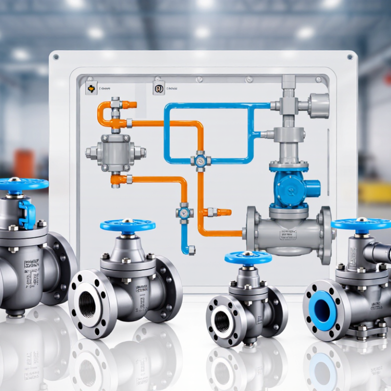
Choose a hydraulic valve by asking what the circuit must control: actuator direction, maximum pressure, or movement speed.
Directional valves route oil to extend or retract a cylinder, or reverse a motor. Check the port arrangement and spool position against the circuit diagram. A mismatch can send oil to the wrong chamber. Small detail.
Pressure-control valves limit or maintain pressure. A relief valve protects the circuit when pressure rises, while a reducing valve limits pressure in a branch. Set the working pressure above the actuator’s normal requirement, but below the lowest-rated component’s limit.
Flow-control valves regulate actuator speed by metering oil. Confirm the required flow and consider whether the load changes during operation; a simple restrictor may not hold speed steady. I still recheck this point, because speed and load are easy to confuse.
The U.S. Department of Energy’s Improving Pumping System Performance sourcebook estimates that pumping systems consume nearly 20% of global electricity demand. That figure covers pumping systems broadly, not hydraulic valves alone, but it shows why unnecessary pressure drops and excess flow deserve attention.
Match valve capacity to measured circuit demand, then verify pressure and flow under real operating conditions. ISO 4413 also provides general requirements for hydraulic fluid power systems, including design and safety considerations.
Choose a valve by checking both its maximum working pressure and its flow capacity at the expected pressure drop. ISO 4413:2010 sets safety requirements for hydraulic systems, and ISO 10770-1:2009 defines test methods for electrically modulated valves. A valve’s pressure rating is not its flow rating. Both must suit the circuit.
For example, an estimated orifice calculation using 10 mm² opening area, 5 MPa pressure drop, 850 kg/m³ oil density, and a discharge coefficient of 0.65 gives about 42 L/min. Treat this as a screening estimate, not a guaranteed catalog value; real flow depends on geometry, oil temperature, and test conditions. If the machine needs 50 L/min, that opening may restrict motion and create heat. Check the manufacturer’s flow-versus-pressure-drop curve, then compare the valve rating with peak system pressure, including transient spikes. That margin matters. I would still verify the result on the actual circuit.
Tips: Match rated flow to demand at the intended pressure drop. Check peak pressure, not just normal operating pressure, and confirm the data sheet’s test conditions.
Choosing a hydraulic valve starts with the fluid, not the port size. Check the datasheet for approved fluid types and seal compatibility. Mineral oil, water-glycol mixtures, and synthetic fluids can affect seals differently. A mismatch may cause swelling, leakage, or early wear.
Viscosity matters across the full operating range. Thick fluid during a cold start can slow spool movement. Thin fluid at high temperatures may increase leakage and reduce lubrication. Compare your fluid’s viscosity at actual operating temperatures with the valve’s specified limits. A workshop test may not reveal what happens on a frosty morning or after hours of heavy use.
Tips: Record the fluid type, viscosity grade, and expected minimum and maximum temperatures before selecting a valve. Check whether the datasheet lists limits for continuous or brief operation. If a value sits close to a limit, ask the supplier to confirm suitability. Small details matter.
Real systems rarely hold one steady temperature. Measure near the valve, not only at the reservoir, because local heat can build around pumps and restricted lines. Also check for additives or contamination that may change fluid behavior. Datasheets are useful, but they cannot account for every installation condition. If your measurements are incomplete, pause before choosing; guessing can be expensive.
When choosing hydraulic valves, treat oil cleanliness as part of the valve specification. ISO 4406 gives three code numbers for particles larger than 4, 6, and 14 micrometres. Lower numbers indicate cleaner oil. An 18/16/13 cleanliness target is often used for sensitive servo systems, where small particles can affect clearances and response. It is a target, not a universal rule.
Match the required cleanliness level to the valve maker’s published limits and the whole system design. A proportional or servo valve may need cleaner oil than a robust directional valve. Check the filter rating, reservoir condition, and flushing procedure together. A clean filter alone does not guarantee clean oil. Sampling technique matters, too; a dirty bottle or sampling point can distort particle counts. I have seen a good-looking result become less convincing after a repeat sample.
Tips: Take samples from a live, well-mixed flow, not the bottom of a cold reservoir. Record the machine’s operating hours and filter changes. If readings drift, investigate the cause before simply installing a finer filter. A finer element may increase pressure drop or bypass risk. Keep records. Small details count.
ISO 4406 code 18/16/13 corresponds to particle-count bands of 1,300–2,500 particles/mL at ≥4 µm(c), 320–640 particles/mL at ≥6 µm(c), and 40–80 particles/mL at ≥14 µm(c). These are cumulative particle counts; check the valve or system manufacturer's cleanliness requirement before setting a target.
When choosing a hydraulic valve, verify its electrical interface against the machine’s actual supply and control system. Check coil voltage, AC or DC type, current draw, connector pinout, and whether the controller can handle the load. A connector that fits may still be wired differently. Small mismatches matter. Compare the valve datasheet with the wiring diagram, then confirm the details at the terminals before energizing the system.
ISO 4413 sets safety principles for hydraulic systems, including safe integration of components and control functions. It does not replace electrical design checks. Consider what happens if power fails, a signal is lost, or a coil overheats. The valve’s response should not create unexpected movement or leave trapped pressure without a safe means of control. Check pressure limits, isolation procedures, and any required protective measures as part of the machine-level risk review. It is easy to treat a wiring diagram as proof; it is not.
During commissioning, test the valve under controlled conditions. Confirm the commanded direction, response time, and behavior during shutdown. Record the measured supply voltage and observed results for maintenance staff. A detail can be missed, even with careful paperwork, so have another qualified person review critical connections and safety assumptions.
| Verification Dimension | What to Check | Practical Selection Guidance | Safety and Documentation Check |
|---|---|---|---|
| Valve function and circuit role | Confirm whether the application requires directional, pressure-control, or flow-control functionality, and identify the required valve position and actuation method. | Match the valve symbol and operating states to the hydraulic schematic. Check whether the valve is normally open, normally closed, or has another defined neutral condition. | Review the complete circuit for hazardous movement, pressure trapping, and the effects of loss of electrical power or hydraulic supply. |
| Operating pressure | Check the maximum working pressure, return-line pressure limit, and any pressure peaks or transient loads. | Select a valve whose rated limits are suitable for the actual system conditions. Do not use nominal system pressure alone if transient pressure can be higher. | ISO 4413 calls for hydraulic systems and components to be selected and used within their rated limits. Verify pressure limits in the valve documentation and system design. |
| Flow capacity and pressure drop | Compare required flow with the valve’s rated flow and pressure-drop data for the intended fluid and operating conditions. | Check the manufacturer’s flow curves where available. Excessive pressure drop can generate heat and reduce actuator performance. | Confirm that the selected flow capacity does not create unsafe or unpredictable actuator speed or system behavior. |
| Electrical supply type | Verify whether the coil is designed for AC or DC operation and confirm the rated voltage and permitted voltage range. | Match the coil rating to the actual control supply. A 24 V DC supply is common in machinery, but it is not universal and must not be assumed. | Check the valve data sheet and control-system drawings before connection. Do not energize a coil from a supply of the wrong type or rating. |
| Coil current and power | Check the coil’s rated current or power and the output capacity of the controller, relay, and power supply. | For a DC coil, estimated current can be calculated as power divided by voltage; for example, a 24 V DC, 18 W coil draws about 0.75 A at its rated conditions. | Allow for the stated electrical characteristics, switching behavior, and any additional loads on the same supply. Use the manufacturer’s specified values for final design. |
| Duty rating and thermal limits | Check the permitted energized time, switching frequency, ambient temperature, and coil temperature limits. | Choose a coil duty rating suitable for the real operating cycle. Continuous energization requires a coil rated for continuous duty under the stated conditions. | Consider heat from adjacent equipment and enclosure conditions. Verify that the intended duty does not exceed the documented thermal limits. |
| Connector and wiring | Confirm connector type, pin assignment, cable size, polarity requirements, and available space for wiring and servicing. | Match the connector and wiring arrangement to the control panel and installation. Follow the terminal diagram supplied for the specific coil and connector. | Protect wiring from abrasion, heat, fluid exposure, and mechanical damage. Ensure electrical connections can be inspected and maintained safely. |
| Ingress protection and environment | Check the specified enclosure protection rating and suitability for dust, water, vibration, temperature, and other site conditions. | Select a protection level appropriate to the installation. An IP rating describes protection against ingress under defined test conditions; it does not by itself establish suitability for every environment. | Verify the complete installed assembly, including connectors and cable entries, rather than relying only on the coil rating. |
| Coil suppression and control outputs | Check whether suppression is built into the coil or connector and whether the control output is compatible with it. | Confirm polarity for DC coils fitted with a diode or other polarity-sensitive suppression. Check that suppression does not cause unacceptable release delay in the control circuit. | Follow the control-device and valve documentation. Do not add suppression components without confirming their effect on switching and safety functions. |
| Loss of power and safe state | Determine the valve’s hydraulic state when the coil is de-energized, and assess the consequences of power failure or a broken wire. | Choose a spring-return, detented, or other configuration based on the required circuit behavior. A valve’s de-energized state alone does not guarantee that a machine is safe. | Assess the complete machine for unintended movement and stored energy. Provide suitable risk-reduction measures, isolation, and pressure-release provisions as required by the system design. |
| Emergency stop and safety controls | Check how the valve interacts with emergency-stop functions, interlocks, and other machine safety controls. | Do not assume that a standard solenoid valve is a safety-rated component. Select and validate safety-related control measures for the required machine risk reduction. | Coordinate the hydraulic design with the machine risk assessment and applicable electrical and machinery safety requirements. Verify the complete safety function. |
| Fluid and materials | Verify fluid type, viscosity range, cleanliness requirements, seal compatibility, and operating temperature. | Use only fluids and conditions permitted by the valve documentation. Confirm compatibility of seals and wetted materials with the chosen hydraulic fluid. | Maintain fluid cleanliness and follow installation and maintenance instructions to reduce malfunction and unexpected system behavior. |
| Installation and maintenance | Check mounting position, port identification, tightening requirements, access for service, and procedures for electrical and hydraulic isolation. | Install according to the valve and system documentation. Label ports and electrical connections where needed to reduce wiring and plumbing errors. | Before maintenance, isolate energy sources and safely release or restrain stored hydraulic energy. Follow documented lockout and servicing procedures. |
| Final verification | Compare the selected valve, coil, connector, and control output against the approved schematic and component documentation. | Record model specifications, pressure and flow ratings, voltage, current or power, duty rating, connector details, and environmental limits. | Review the hydraulic system against the applicable edition of ISO 4413 and assess other applicable standards and local regulations for the machine. |
Important: ISO 4413 addresses safety requirements for hydraulic fluid power systems; it does not replace component documentation or a machine-specific risk assessment. Confirm ratings and installation requirements from the selected valve and electrical-control documentation.