skip to Main Content

10 Best Pressure Reducing Valves for Industrial Use

Choosing the right pressure reducing valves can protect industrial equipment, stabilize downstream processes, and reduce pressure-related wear. Yet a valve that performs well on a clean water line may struggle with steam, compressed air, or a changing flow rate. Details matter.

This guide examines 10 pressure reducing valves designed for industrial use, comparing practical features rather than treating one model as best for every plant. Key considerations include inlet pressure, required outlet pressure, flow capacity, fluid temperature, body materials, connection type, and maintenance access. A gauge port or clear adjustment mechanism can make commissioning easier. Reliable documentation matters, too. Small omissions can become expensive surprises.

A sound choice starts with the system’s actual operating conditions and the manufacturer’s sizing data. Check whether the valve can handle both normal demand and expected pressure fluctuations. Consider installation space, service intervals, and available replacement parts. There is no effortless shortcut. Even a well-reviewed valve may be unsuitable if its capacity or materials do not match the application. This comparison offers a starting point, not a substitute for engineering review. A little uncertainty remains: real systems change, and specifications do not always capture every field condition. Recheck the selection before installation.
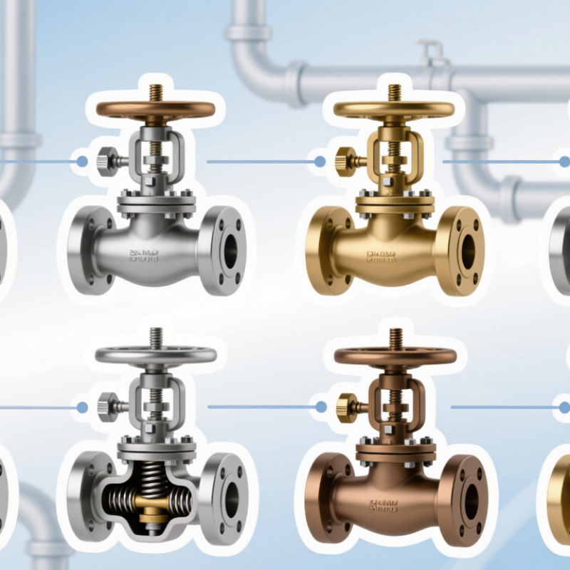
10 Best Pressure Reducing Valves for Industrial Use

Industrial PRV Basics: Inlet Pressure, Setpoint, and Outlet Control

10 Best Pressure Reducing Valves for Industrial Use

Industrial PRV Basics: Inlet Pressure, Setpoint, and Outlet Control

A pressure reducing valve (PRV) lowers higher inlet pressure to a controlled downstream level. Start by checking the inlet pressure range, not just its normal reading. Supply pressure can shift during startup or when nearby equipment draws flow. The valve must also handle the required flow without excessive outlet-pressure drop. A gauge on each side makes commissioning and troubleshooting more grounded in real readings.

The setpoint is the target outlet pressure under specified operating conditions. Adjust it gradually, then check the downstream gauge while the system is flowing. An idle reading can be misleading. A setpoint that looks perfect at low demand may drift when production ramps up. Outlet control also depends on correct sizing, clean fluid, and the valve’s operating range; a pressure reducing valve cannot compensate for every system problem.

Direct-Acting vs. Pilot-Operated PRVs: Flow, Accuracy, and Droop

Direct-acting PRVs use process pressure to move the plug, so their response is simple and immediate. As flow rises, outlet pressure often falls: this is droop. That matters. A compact valve may suit a small branch, but its pressure can sag when several machines start together.

Pilot-operated PRVs use a smaller pilot valve to control the main valve. This arrangement can handle higher flows and hold pressure more closely across changing demand. It also adds sensing lines, moving parts, and a minimum differential-pressure requirement. A blocked sensing line can undermine control. Pilot-operated does not automatically mean better.

For gas service, EN 334:2019 defines regulator accuracy classes including AC 1 and AC 2.5; the lower figure indicates a tighter permitted outlet-pressure deviation. The standard also classifies lock-up performance, when flow stops. These figures are useful selection benchmarks, not a promise of identical results in every installation. Check the valve’s certified capacity curves against inlet pressure, set pressure, and peak demand. A practical test should record outlet pressure at low, normal, and maximum flow. I would not choose on accuracy class alone; piping losses and poor sensing-point placement can erase the expected advantage.

10 Industrial PRVs Compared by Media, Pressure Range, and Materials

Industrial pressure reducing valves differ most in the media they handle, their operating range, and the materials exposed to that media. A valve suited to clean water may not tolerate hot steam or oil. Compressed air systems often use compact direct-acting designs, while larger, changing flows may call for pilot-operated control. Check the stated inlet and outlet pressure limits, not just the advertised range. Flow capacity matters, too; a valve can meet the pressure target yet struggle when demand rises.

Material compatibility is equally specific. Brass can suit some water and air services, while stainless steel is often selected for corrosive conditions or stricter cleanliness needs. Carbon steel may be practical for many industrial lines, but coating and process conditions deserve scrutiny. Seals also count: elastomers can swell, harden, or lose resilience when exposed to heat or certain fluids. Small details matter. A comparison table is only a starting point; actual media composition, temperature, pressure variation, and maintenance access can change the choice. The neatest specification is not always the best fit. Verify manufacturer data and applicable engineering requirements before installation.

IEC 60534 Sizing: Cv Equals 1 US gpm of Water at 1 psi Pressure Drop

For industrial pressure reducing valves, Cv describes flow capacity, not the valve’s nominal pipe size. In US customary units, one Cv corresponds to one US gallon per minute of water at about 60°F, with a 1 psi pressure drop across the valve. A useful reference point. It does not mean every process fluid will flow at that rate.

IEC 60534 sizing methods use operating conditions to estimate the required valve capacity. Engineers consider inlet and outlet pressures, temperature, fluid density, and expected flow range. For water, a 1 psi drop helps explain the Cv definition; actual plant conditions may involve much larger pressure changes. Gas and steam also require different calculations, including checks for choking and compressibility. A coefficient alone cannot predict stable pressure control.

During selection, compare calculated capacity with the valve’s usable range, not just its maximum Cv. An oversized valve may hunt around the setpoint, while an undersized one can restrict peak demand. Check the pressure readings and fluid data carefully. A spreadsheet can look precise while its inputs are guesses. Even a small error in outlet pressure or flow demand can change the result, so verify assumptions against operating measurements where possible.

Pressure-Reducing Valve Sizing Reference — IEC 60534

Water flow capacity at a 1 psi pressure drop, shown for reference Cv values 1–10.

By definition, Cv is the US gallons per minute of water flowing through a valve at a 1 psi pressure drop. These bars illustrate that definition; they are not product ratings or a ranking. Actual valve sizing requires the applicable IEC 60534 equations and service conditions.

Selection and Care: Check ASME B16.34 Ratings, Lockup, and Maintenance

When comparing pressure reducing valves for industrial service, start with the actual inlet pressure, required outlet pressure, flow range, and fluid temperature. Check the valve’s ASME B16.34 pressure-temperature rating against the system conditions, including credible pressure spikes. A pressure class alone does not confirm suitability at every temperature. Verify the body material, end connections, and trim are compatible with the fluid. Small details matter. A valve sized only for peak flow may regulate poorly during low-demand periods.

Lockup is the outlet pressure reached when downstream flow stops. It may sit above the set pressure, so confirm the expected rise stays within the limits of downstream equipment. Ask for the manufacturer’s stated lockup performance or test data, and compare it with the process requirements. One assumption worth revisiting is that a stable gauge reading during normal flow proves safe shutoff. It does not. Check for pressure creep after demand closes, using a suitable gauge and a controlled test procedure.

Care affects performance as much as selection. Follow the valve’s service instructions and isolate, depressurize, and verify the line before inspection. Check strainers for debris, then examine the seat, diaphragm, spring, and sensing line for wear or blockage. Record outlet pressure and operating conditions before adjustments; small changes can produce noticeable shifts. If results vary, pause and investigate. A worn seat or plugged sensing line can mimic a setpoint problem. Keep maintenance records, but review them critically: repeated adjustments may signal a deeper fault.

Back To Top