 skip to Main Content

What Are the Top 10 Types of Pressure Regulating Valves?
Pressure rarely stays constant as pumps cycle, demand shifts, or equipment starts and stops. Pressure regulating valves help control those changes, protecting pipes and instruments while keeping a system within its intended operating range. Their role may look simple, but choosing the wrong design can cause pressure swings, noise, poor flow, or premature wear.
This guide examines ten common types, including direct-acting and pilot-operated regulators, pressure-reducing and back-pressure valves, differential-pressure designs, and electronic regulators. Some categories overlap, and manufacturers do not always use identical names. That deserves a closer look. A valve’s label alone does not establish whether it suits a particular installation.
Real conditions matter. A regulator handling clean water may behave differently from one serving compressed air or process gas. Flow demand, inlet pressure, required outlet pressure, fluid temperature, and the consequences of failure all affect selection. Even a small pressure drop across a valve can change performance. Installation details matter, too: a blocked sensing line or poorly placed pressure gauge can make troubleshooting harder. The ten types offer a practical starting point, not a substitute for checking manufacturer data and system requirements. Some choices remain less obvious than they seem. A qualified engineer can verify sizing and operating limits before installation.
Pressure Regulators: Definition, Function, and Core Components
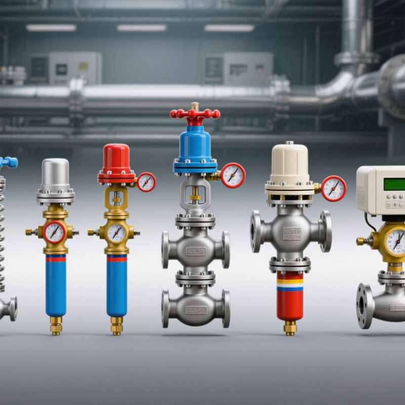
A pressure regulator is a control device that reduces a higher inlet pressure and maintains a selected downstream pressure as demand changes. It does not create pressure; it balances forces inside the valve. When outlet pressure falls, the sensing element moves the valve open. As pressure recovers, it throttles flow. Response depends on the regulator design, inlet conditions, and actual demand.
Core components include the body, seat and plug, spring, diaphragm or piston, and adjustment screw. The spring sets the target pressure, while the diaphragm or piston senses downstream pressure and shifts the plug. A small sensing passage can clog, causing sluggish control. That sounds simple. It isn’t. The U.S. Department of Energy’s 2016 compressed-air sourcebook notes that compressed-air systems can account for about 10% of industrial electricity use, making sound pressure control relevant to efficiency. A regulator alone cannot prevent leaks or poor system design.
Tip: Check the pressure both at the regulator outlet and at the point of use under real flow. A gauge reading with no demand may hide pressure droop during operation. Choose a regulator with a suitable pressure range and flow capacity, then inspect its diaphragm, seat, and connections during maintenance.
What Are the Top 10 Types of Pressure Regulating Valves? — Pressure Regulators: Definition, Function, and Core Components
| Type | How It Regulates Pressure | Typical Applications | Common Core Components | Key Consideration |
|---|---|---|---|---|
| Direct-Acting Pressure-Reducing Regulator | Downstream pressure acts directly on a diaphragm or piston, which moves the valve element to maintain the set outlet pressure. | Low- to moderate-flow air, water, and gas services; building and equipment supply lines. | Body, seat, plug or poppet, spring, diaphragm or piston, and adjustment screw. | Simple and responsive, but outlet pressure can vary as inlet pressure or flow changes. |
| Pilot-Operated Pressure-Reducing Regulator | A pilot valve controls pressure on a main-valve diaphragm or piston, allowing the main valve to handle larger flows. | Higher-flow distribution systems, industrial process lines, and utility services. | Main valve, pilot valve, sensing line, diaphragm or piston, and internal or external passages. | Can provide more accurate control over a wider flow range; requires suitable installation and clean operating fluid. |
| Back-Pressure Regulator | Opens as upstream pressure rises above its set point, releasing fluid to maintain pressure on the inlet side. | Process lines, pump bypass systems, and pressure control upstream of equipment. | Body, seat, valve element, spring, and pressure-sensing diaphragm or piston. | Controls upstream pressure; it is not the same as a pressure-reducing regulator, which controls downstream pressure. |
| Differential-Pressure Regulator | Senses pressure on both sides of a diaphragm or piston and adjusts the valve to maintain a chosen pressure difference. | Hydronic heating and cooling circuits, filtration systems, and process equipment requiring a controlled pressure drop. | Valve body, diaphragm or piston, spring, sensing ports, and valve element. | Correct sensing connections and adequate pressure differential are essential for stable control. |
| Dome-Loaded Regulator | Pressure applied to a loading dome supplies the control force, often instead of or in addition to a mechanical spring. | Automated process systems and applications needing remote or adjustable pressure control. | Regulator body, diaphragm or piston, valve element, loading dome, and pilot-pressure connection. | Control depends on the loading-pressure source and its stability; some designs are available in reducing or back-pressure configurations. |
| Electronic Pressure Regulator | An electronic controller reads a pressure sensor and adjusts an electrically actuated valve to reach the set point. | Automated manufacturing, test equipment, and processes requiring programmable pressure settings. | Pressure sensor, controller, actuator, control valve, and electrical connections. | Offers remote adjustment and control features, but requires power and appropriate sensor calibration. |
| Gas Pressure Regulator | Uses a diaphragm- or piston-operated valve to reduce gas supply pressure to a controlled outlet pressure. | Gas distribution, burners, laboratory equipment, and industrial gas supply systems. | Gas-compatible body, seat, valve element, spring, diaphragm, and vent or sensing passage. | Must be selected for the gas, pressure range, flow demand, and applicable safety requirements. |
| Water Pressure-Reducing Valve | Throttles incoming water flow in response to downstream pressure to maintain a lower outlet pressure. | Building water services, irrigation systems, and equipment supplied from higher-pressure mains. | Body, seat, disc or piston, spring, diaphragm or piston, and adjustment mechanism. | Inlet pressure, flow demand, water quality, and local plumbing requirements affect selection and performance. |
| Steam Pressure-Reducing Valve | Reduces steam pressure by modulating the flow through a valve in response to downstream pressure. | Steam distribution branches, heating systems, and industrial process equipment. | Steam-rated body and trim, seat, valve plug, spring or pilot, diaphragm or piston, and sensing connection. | Selection must account for steam temperature, capacity, pressure drop, condensate management, and noise. |
| Vacuum Regulator | Admits gas or air, or controls a vacuum line, to maintain a selected sub-atmospheric pressure. | Vacuum packaging, laboratory systems, suction equipment, and process vacuum control. | Body, diaphragm, spring, valve element, adjustment mechanism, and vacuum sensing passage. | Designed for vacuum service; confirm the regulator’s operating direction, leakage performance, and compatible materials. |
Note: These categories describe different control methods, functions, or service media, so some overlap. For example, a gas or steam regulator may use a direct-acting or pilot-operated design. The appropriate choice depends on the fluid, inlet and outlet pressures, required flow, accuracy, and installation conditions.
Related Posts
-
What Are the 2026 Top Types of Pressure Reducing Valves?
-
Top 10 Hydraulic Pressure Relief Valves for Global Buyers?
-
Why Are Pressure Control Valves Important?
-
Unlocking Efficiency: How Hydraulic Directional Control Valves Boost Industrial Performance by 30%
-
Top 10 Hydraulic Check Valves You Should Know About?
-

Top 10 Benefits of Using Automated Valves in Industry