skip to Main Content

Why Are Proportional Valves Used in Hydraulic Systems?

Why do hydraulic systems use proportional valves? The answer is control. Unlike a basic on/off valve, a proportional valve can vary flow or pressure in response to an electrical command. That lets a machine move at a chosen speed, rather than lurching between stopped and full movement. A loader arm, injection-molding clamp, or test-rig cylinder can respond more smoothly. Small changes matter. They can improve positioning, reduce shock loads, and help operators coordinate several functions. On a production line, a clamp can close gently before applying full force, rather than striking the workpiece.

Inside the valve, an actuator shifts a spool or adjusts a metering element. The resulting opening regulates hydraulic oil, while sensors and a controller may refine the command in demanding systems. This flexibility is useful where loads change or motion must be repeatable. Yet the commanded signal and actual movement can differ under changing loads. It is not magic. Performance depends on correct valve sizing, clean oil, suitable controls, and careful commissioning. A poorly tuned system may hunt, heat the oil, or respond slowly. Proportional valves also cost more than simple directional valves and may require skilled maintenance. Their value depends on the task: when smooth, adjustable motion matters, they offer precise control; for basic full-speed movement, a simpler valve may be enough. A practical design starts with the cylinder or motor, its load, and the required response—not with the valve alone.
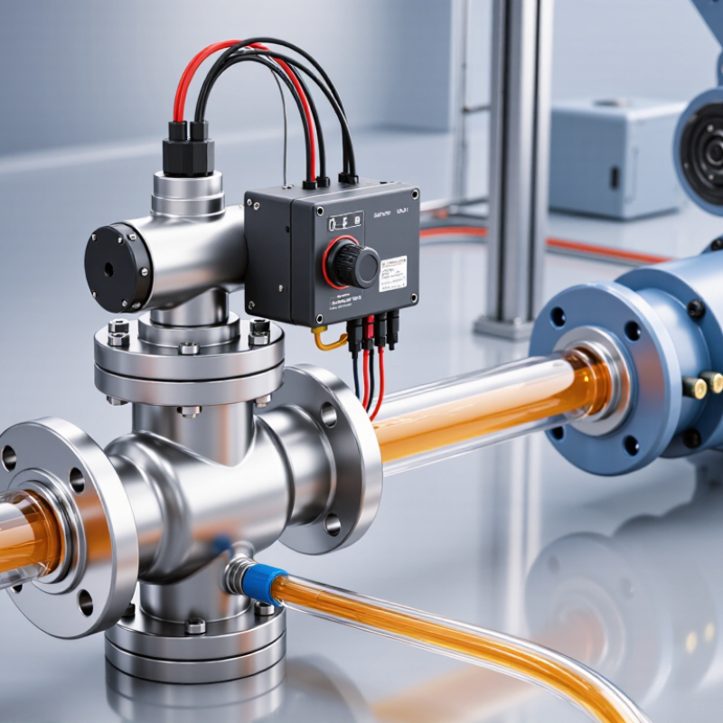
Why Are Proportional Valves Used in Hydraulic Systems?

Control principle: 0–10 V and 4–20 mA signals enable continuous adjustment

Proportional valves convert electrical commands into adjustable spool positions, rather than simply switching fully open or closed. A controller sends a 0–10 V or 4–20 mA signal to regulate flow or pressure continuously. Small changes matter. As the command shifts, the valve meters oil to adjust cylinder speed or motor response. A 4 mA live zero can help distinguish a valid minimum command from a broken wire. Voltage inputs are straightforward, but long cables and electrical noise can affect signal accuracy.

Signal choice is only part of the control setup. The controller’s output range, valve input scaling, and machine response must match. A valve may react sluggishly if its deadband or settings are poorly adjusted. Commissioning takes care. The U.S. Department of Energy’s 2006 report, Improving Pumping System Performance: A Sourcebook for Industry, cites potential energy savings of 20–50% from pumping-system optimization. That figure describes system-level opportunities, not guaranteed savings from proportional valves. In practice, continuous control can help avoid unnecessary flow, but poor sizing or tuning can still waste energy.

Valve behavior: proportional control varies flow or pressure, unlike on/off switching

An on/off directional valve sends fluid along a fixed path or stops it. A proportional valve changes spool position gradually, adjusting flow or pressure as the electrical command changes. That is the key difference. At a loader, a small joystick movement can produce a slow boom lift; a larger movement can raise it faster. The operator gets finer motion, not merely open-or-shut behavior. Limits remain. Oil temperature, changing loads, and valve response can make actual movement differ from the command.

The U.S. Department of Energy and Hydraulic Institute’s report, Improving Pumping System Performance: A Sourcebook for Industry, says pumping systems account for nearly 20% of global electricity use. That figure describes pumping broadly; it does not measure savings from proportional valves. When properly sized and tuned, proportional control can match actuator flow to demand and reduce avoidable throttling or abrupt starts. But a proportional valve cannot fix an oversized pump, a leaking cylinder, or contaminated oil. Circuit design matters more than the valve alone. In practice, commissioning may take repeated adjustment. A neat schematic rarely shows that.

Performance data: response times commonly range from tens to hundreds of milliseconds

Proportional valves let a hydraulic system vary flow or pressure rather than switch only between open and closed. That makes it possible to move a cylinder smoothly, adjust its speed, or hold a load with finer control. The motion still takes time to develop. Valve response times commonly range from tens to hundreds of milliseconds, depending on the design and test conditions.

That is not instant. A command signal must move the spool, and oil must fill the lines and act on the load. Fluid temperature, operating pressure, hose length, and actuator mass can all affect the measured response. A valve tested on a bench may react faster than the same valve in a machine with long hoses and a heavy attachment. The difference can show up when a lift starts: the control signal changes, but the cylinder may lag slightly before moving.

It matters. In a fast positioning task, even a short delay can cause overshoot if the controller reacts too aggressively. For slower equipment, the same delay may be barely noticeable. Engineers should compare response figures only when the measurement method and operating conditions are clear. A published number is useful, but it does not tell the whole story. The system’s actual response needs checking under its working load.

Why Are Proportional Valves Used in Hydraulic Systems?

Their electrical control enables smooth, adjustable hydraulic flow or pressure. Response times commonly fall within tens to hundreds of milliseconds.

Illustrative reference points within the commonly encountered range, not guaranteed specifications. Actual response depends on valve design, drive electronics, operating conditions, and test method.

System design: check rated pressure, flow, hysteresis, and ISO 4406 fluid cleanliness

Proportional valves let hydraulic systems adjust flow and direction in response to an electrical signal. Their performance depends on more than nominal capacity. Check rated pressure and flow against the real operating point, including pressure drops, oil temperature, and expected load changes. A valve rated for the circuit’s peak pressure may still deliver inadequate flow at that pressure. Small details matter.

Hysteresis describes the difference in valve response as the control signal rises and falls. Ask for test data under conditions close to your application, rather than relying on a single catalogue figure. ISO 10770-1:2009 sets out test methods for electrically modulated four-way directional flow-control valves, offering a useful basis for comparing performance. Hysteresis matters.

Fluid cleanliness needs equal attention. ISO 4406:2021 classifies particle contamination by counts at three size thresholds. For example, code 18/16/13 corresponds to about 1,300–2,500 particles per millilitre at 4 μm(c), 320–640 at 6 μm(c), and 40–80 at 14 μm(c). These figures describe a cleanliness class, not a universal target for every valve. Match the required class to the valve’s specification, then verify it with a representative oil sample. I would not assume one clean sample proves the circuit stays clean; contamination can enter during servicing or through poor storage.

Applications and trade-offs: precision control versus added cost and tuning needs

Proportional valves vary flow or pressure in response to an electrical signal, letting an operator slow a cylinder near a fixture or adjust clamping force without repeated on-off cycling. That precision is useful in presses, mobile equipment, and test rigs where sudden movement can damage parts.

Small changes matter.

The U.S. Department of Energy’s Improving Pumping System Performance sourcebook estimates that optimizing pumping systems can reduce energy use by 20–50%. That figure covers system-level measures, not proportional valves alone; valve selection must match the pump, load, and control strategy.

The trade-off is real. Proportional valves cost more than basic directional valves and need commissioning: technicians must tune the command signal, ramp, and feedback against the actual load. A poorly tuned spool may hunt, warm the oil, or make a cylinder creep instead of settle. Filtration and oil condition also affect repeatability.

ISO 10770-1:2015 provides test methods for electrically modulated directional valves, but bench results cannot capture every installation’s hose length, temperature, or load variation.

Keep that in mind.

A valve that performs smoothly on a test stand may need retuning after installation, and the added control hardware can be unnecessary when simple end-stop motion is all the machine requires.

Back To Top