skip to Main Content
Why Is Tungsten Alloy Turning So Difficult?
Tungsten Alloy Turning challenges even experienced machinists because the material combines extreme density, hardness, and abrasive microstructure. Tungsten heavy alloys commonly reach densities between 17 and 19 g/cm³, according to ASM International material references. Their tungsten particles resist deformation, while the nickel-iron or nickel-copper binder behaves differently during cutting. The result is uneven tool loading. A cutting edge may appear sharp, then chip suddenly.
The U.S. Geological Survey’s Mineral Commodity Summaries 2025 identifies tungsten as a critical industrial material and reports that China supplies roughly four-fifths of global mine production. That concentration reflects tungsten’s strategic value, but it also highlights the need for reliable machining knowledge. Dr. E. O. Ezugwu, a recognized researcher in difficult-to-machine alloys, stated, “High cutting temperatures accelerate tool wear and damage the machined surface.” His observation applies strongly here. Heat is only part of the problem.
In a real workshop, a carbide insert can leave a bright, smooth surface on one pass and produce torn edges on the next. Excessive feed may create vibration. Excessive speed may cause rapid flank wear. Abrasive tungsten grains can act like thousands of tiny grinding particles against the tool edge. Coolant helps, but it cannot correct poor workholding or unstable parameters. This explanation remains incomplete without considering alloy composition, grain size, insert geometry, and machine rigidity. Tungsten Alloy Turning is difficult because several small failures often appear together. The process demands measured testing, not assumptions.
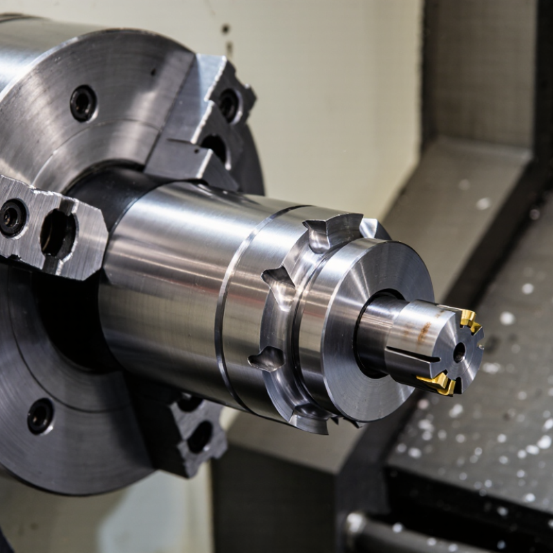
Tungsten alloy is difficult to turn because its microstructure resists ordinary cutting action. Many grades contain hard tungsten particles within a nickel-iron or copper-based binder. These particles behave like tiny abrasive stones against the cutting edge. The workpiece may also show high strength, limited ductility, and unpredictable chip formation.
Heat control creates another problem. Tungsten conducts heat differently from the surrounding binder, so temperature can concentrate near the tool tip. A sharp edge may suddenly chip instead of wearing gradually. Cutting forces rise quickly when the tool becomes dull. The finished surface can then show torn areas, small pits, or vibration marks.
In practical turning, rigid fixturing matters greatly. Even slight tool overhang can amplify chatter. I have found that extremely light feed rates are not always safer. They may rub the surface, build heat, and harden the cutting zone. A controlled feed, suitable cutting geometry, and frequent tool inspection usually provide better control. Still, results vary between alloy grades. This is where machining plans often need revision. No single speed or feed value works reliably for every tungsten alloy.
Why Is Tungsten Alloy Turning So Difficult?
Cutting Forces and Heat Generation During Tungsten Alloy Machining
Tungsten alloy turning is difficult because the material resists deformation under the cutting edge. Its high density and hardness create heavy cutting forces, especially during interrupted cuts. Tool pressure can rise suddenly when the insert meets a hard tungsten-rich zone. This may cause edge chipping, vibration, or poor dimensional control. The machine sounds different. That sound matters.
Heat is another major concern. Tungsten alloy conducts heat differently from common steels, so heat can remain concentrated near the cutting zone. A small contact area may develop a bright, hot streak. Excessive speed increases friction and accelerates tool wear. However, reducing speed too much can worsen rubbing and produce more heat. The correct balance depends on alloy composition, tool geometry, feed rate, and workholding stiffness. There is no universal setting. That is easy to forget.
Tips: Use a rigid setup and minimize tool overhang. Select a tough cutting edge with suitable clearance. Begin with conservative cutting parameters, then adjust one variable at a time. Apply steady coolant if the process allows it, and avoid sudden thermal changes. Check cutting forces, surface temperature, and edge wear after each trial. In practice, the first setup is rarely perfect. Careful records often reveal that vibration, rather than speed, caused the failure.
| Data Dimension | Representative Value or Range | Unit | Machining Significance |
|---|---|---|---|
| Tungsten content in heavy alloy | 90–97 | wt% | The high tungsten fraction provides excellent density and stiffness, but it also makes cutting more abrasive and force-intensive. |
| Density | 17.0–18.5 | g/cm³ | The high mass density increases the energy required to accelerate and remove each unit of material. |
| Elastic modulus | 300–360 | GPa | High stiffness limits elastic deformation but increases resistance to chip formation and raises the load on the cutting edge. |
| Typical hardness | 250–350 | HV | Hard tungsten-rich grains can cause abrasive flank wear, edge chipping, and rapid loss of tool sharpness. |
| Thermal conductivity | 50–100 | W/m·K | Usually lower than pure tungsten and strongly dependent on binder composition; heat can remain concentrated near the cutting zone. |
| Coefficient of thermal expansion | 5–7 | ×10⁻⁶/K | Low expansion helps dimensional stability, but steep thermal gradients can still produce local distortion and residual stress. |
| Specific cutting force during turning | 2,500–4,500 | N/mm² | A representative engineering range for sharp carbide turning; the actual value changes with alloy grade, tool geometry, wear, feed, and cutting speed. |
| Recommended initial cutting speed | 15–40 | m/min | A conservative starting range for carbide turning; excessive speed rapidly increases tool temperature and flank wear. |
| Finishing feed rate | 0.03–0.12 | mm/rev | Lower feed reduces chip thickness and cutting force, helping protect the edge and improve surface finish. |
| Roughing feed rate | 0.08–0.20 | mm/rev | Higher feed improves material removal rate but can increase mechanical shock, vibration, and insert chipping. |
| Typical depth of cut for initial trials | 0.2–1.0 | mm | A modest radial depth of cut helps control cutting force and thermal load while the process is being optimized. |
| Illustrative cutting force | 375 | N | Example calculated from 3,000 N/mm² specific cutting force × 0.10 mm feed × 1.25 mm effective chip width; actual force must be measured or validated experimentally. |
| Illustrative mechanical cutting power | 0.19 | kW | Calculated as P = Fc × Vc: 375 N × 0.50 m/s at 30 m/min cutting speed. |
| Heat carried by the chip | Approximately 60–80 | % of generated heat | The chip removes much of the heat, but the remaining heat entering the tool and workpiece can still cause rapid wear and thermal damage. |
| Main tool-wear mechanisms | Abrasive flank wear, crater wear, edge chipping, and thermal cracking | — | Hard tungsten-rich particles abrade the tool, while interrupted contact and thermal cycling can fracture the cutting edge. |
| Process-control priority | Rigid setup, sharp positive cutting edge, stable coolant delivery, and continuous engagement | — | These controls reduce vibration, prevent thermal shock, and limit the sudden force changes that commonly damage the tool. |
Note: Values are representative engineering ranges for tungsten heavy alloys containing approximately 90–97 wt% tungsten. Exact behavior depends on tungsten content, binder chemistry, microstructure, heat treatment, tool material, insert geometry, coolant strategy, and machine rigidity.
Why Is Tungsten Alloy Turning So Difficult?
Tool Wear Mechanisms in Tungsten Alloy Turning
Tungsten alloy turning is difficult because its structure attacks the cutting edge in several ways. Hard tungsten particles create severe abrasive wear along the flank. The edge becomes dull before the workpiece surface looks damaged. Small chips may also break the edge suddenly.
Heat makes the problem less predictable. Tungsten conducts heat differently from common machining alloys, while the cutting zone can develop intense local temperatures. This encourages diffusion and adhesion between the tool and workpiece. A built-up edge may form, detach, and remove tiny pieces of tool material. The damage often appears as a bright notch near the cutting depth.
In practical turning trials, rigid fixturing and a sharp, properly supported tool matter greatly. Excessive cutting speed usually accelerates crater wear and edge chipping. Interrupted cuts are especially harsh. Abrasive particles repeatedly strike the cutting edge. Keep the cutting engagement steady.
That point is easy to miss.
Tool wear is not controlled by speed alone. Feed, depth of cut, tool geometry, coolant delivery, and workpiece composition interact continuously. A coating may reduce adhesion, but it cannot compensate for vibration or poor chip control. My early assumption was that lower speed always protected the tool. That explanation was incomplete. Low speed can increase rubbing, heat concentration, and built-up edge formation. Monitoring flank wear, notch depth, and cutting forces gives a more reliable picture than surface appearance alone.
Why Is Tungsten Alloy Turning So Difficult?
Workpiece Defects Caused by Improper Turning Conditions
Tungsten alloy resists cutting because it combines high hardness, density, and limited ductility. Improper turning conditions quickly create visible workpiece defects. Excessive cutting speed can generate heat, soften the cutting edge, and leave a rough, discolored surface. A feed rate that is too high may produce deep tool marks, burrs, or chipped edges. I have also seen small setup errors cause serious dimensional changes after only a few passes.
Workholding requires careful attention. Weak clamping can create vibration, commonly called chatter. Chatter leaves repeating waves along the diameter and may cause microcracks near the shoulder. Excessive tool engagement creates similar problems. A worn insert often rubs instead of cutting, raising cutting forces and damaging the surface. These defects are not always obvious immediately. Measurement after cooling is essential because thermal expansion can hide the true final dimension.
Tips: Use a rigid setup, sharp geometry, and conservative cutting parameters. Reduce the depth of cut when vibration appears. Keep coolant directed at the cutting zone, not merely nearby. Check tool wear frequently, even when the edge looks acceptable. In practice, I would rather remove less material per pass than repair a cracked workpiece. That approach feels slower, but it usually protects accuracy and tool life. One detail is easy to overlook: interrupted cuts can turn a stable process into a harsh impact within seconds.
Workpiece defects are commonly associated with excessive heat, interrupted cutting, high cutting forces, poor chip evacuation, and inadequate cooling. The chart shows representative defect-incidence values for non-optimal turning conditions.
Defect incidence is expressed as the percentage of inspected workpieces showing the listed defect under each turning condition. Lower cutting speed, controlled feed rate, rigid tooling, and effective coolant application generally help reduce these defects.
Tungsten alloy is difficult to turn because it combines extreme density with high thermal resistance. The U.S. Geological Survey’s Mineral Commodity Summaries 2024 lists tungsten’s density near 19.3 g/cm³ and melting point around 3,422°C. These properties increase cutting forces and concentrate heat near the tool edge. The material may also produce short, abrasive chips. Keep it steady.
A rigid machine setup is essential. Minimize tool overhang, secure the workpiece firmly, and check runout before cutting. Use a sharp carbide insert with a positive rake angle. Moderate cutting speed, controlled feed, and shallow passes usually reduce edge chipping. Avoid dwelling, because rubbing can harden the surface and damage the insert. Flood coolant may help, but unstable coolant flow can cause thermal shock. That detail is often overlooked.
Tool life should be measured systematically under ISO 3685 tool-life testing principles. Record flank wear, cutting force, surface roughness, and chip shape after each trial. Start conservatively, then adjust speed in small steps. A 10% speed reduction may improve tool life, but it can also increase rubbing. The best setting is not always the slowest one. In practice, operators sometimes trust general cutting charts too much. Tungsten alloy grades vary, and their binder content changes machining behavior. Small trials remain necessary.
