skip to Main Content
Choosing among the top Machine Vision Inspection systems requires more than comparing cameras, software, and advertised speeds. In practice, the best system fits the production line, product surface, lighting conditions, and inspection risk. A camera may detect a clear scratch on polished metal, yet struggle with reflective plastic or uneven labels. Small details matter.
This guide examines leading systems through practical performance, integration quality, accuracy, and long-term reliability. It considers image resolution, processing speed, artificial intelligence tools, operator usability, and support services. It also looks at how systems perform beside conveyors, robotic arms, sensors, and factory networks. A technically impressive platform can still disappoint when setup takes hours or false rejects interrupt production.
The answer is not obvious. A glossy demo can mislead. Real factories contain dust, vibration, changing light, and product variation. Experienced engineers often test sample parts under difficult conditions before approving a purchase. That approach reveals weaknesses early, although it cannot predict every future production change. Cost deserves careful attention, too. A low initial price may hide training, maintenance, software, or replacement expenses. Conversely, an expensive system may offer unnecessary features for a simple inspection task.
By comparing established manufacturers and specialized solutions, this overview aims to support informed decisions. It does not assume one universal winner. The strongest choice depends on measurable requirements, verified results, and the people responsible for daily operation. Reliable inspection begins with evidence, not impressive claims.
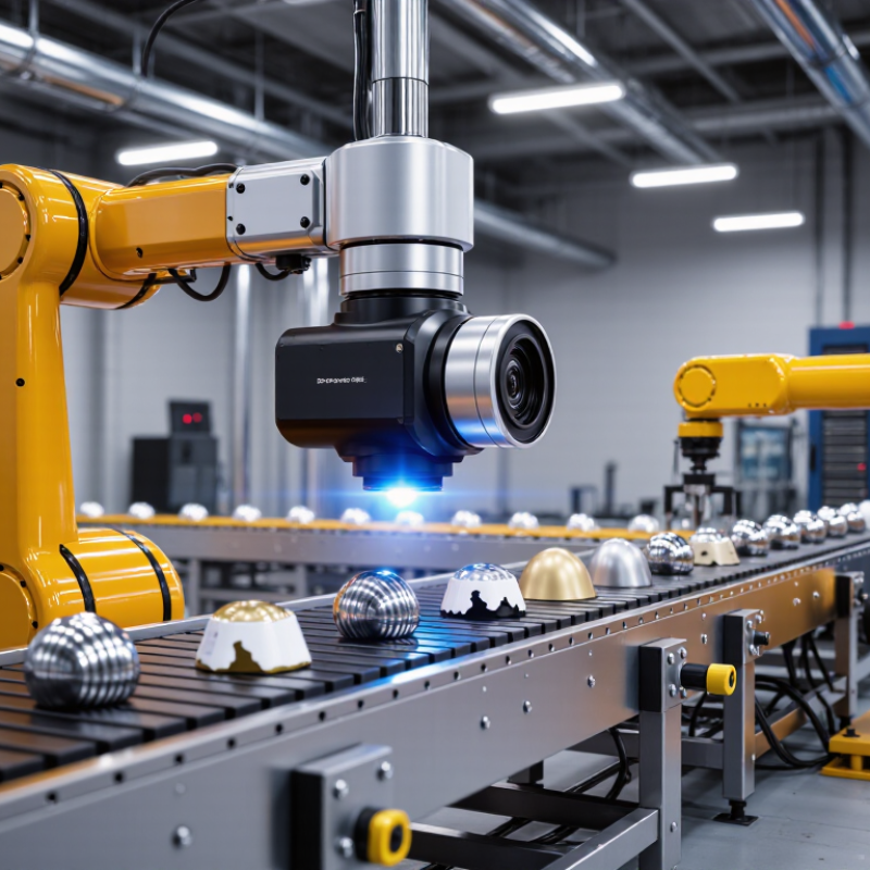
2D area-scan systems with 4K resolution are strong choices for surface-defect inspection. A 4K sensor captures fine scratches, dents, stains, and coating gaps across a wide field of view. This detail helps inspectors detect defects that standard cameras may overlook. However, resolution alone does not guarantee reliable results. Lens selection, lighting geometry, conveyor stability, and image contrast matter just as much.
In production trials, controlled lighting often delivers the biggest improvement. Low-angle illumination can reveal raised scratches, while diffuse lighting reduces glare on polished parts. A fixed camera position also supports repeatable measurements. Inspection software should compare images against validated samples, not unrealistic perfect surfaces. I have found that overly sensitive settings create false alarms. Operators then lose trust in the system. That problem is easy to underestimate.
Tips: Keep the inspected surface clean before testing. Calibrate the camera regularly. Record defect size, position, and frequency. Test the system with real production variation, including dust, minor color changes, and acceptable marks. A short pilot run may expose weaknesses that laboratory samples hide. No setup is perfect. Review failed images with experienced inspectors, and adjust thresholds carefully rather than chasing every visual difference.
3D vision inspection systems capture depth, not just surface contrast. They use laser triangulation or structured light to build a three-dimensional point cloud. Each point can reveal a height difference measured in micrometers. This supports shape verification for machined parts, molded components, and precision assemblies.
MarketsandMarkets estimates that the global 3D machine vision market could grow from about USD 2.1 billion in 2023 to USD 3.7 billion by 2028. Its forecast indicates a compound annual growth rate near 11.8%. Grand View Research also identifies manufacturing quality control as a major application area. These figures reflect rising demand for automated dimensional checks. Yet market growth does not guarantee reliable inspection.
The difficult part is repeatability. A clean metal surface may scatter projected light unpredictably. Vibration can shift a measured edge by several micrometers. Calibration targets, stable lighting, and controlled conveyor speed therefore matter as much as camera resolution. In practice, engineers compare point clouds against a tolerance model, then flag warpage, missing material, or incorrect assembly height. A millimeter-scale defect is easy to detect. A ten-micrometer deviation is not.
Experience also exposes a weakness: higher resolution can increase noise. More data is not always better data. Operators should validate repeatability across temperature changes, surface finishes, and production speeds. The inspection report should record uncertainty, not only pass or fail. That detail builds trust.
Reference depth scales commonly used when verifying surface texture, fine edges, small steps, and larger geometric features. Values are shown in micrometres (µm).
A 3D vision inspection system converts surface height into depth data. A 10 µm change equals 0.01 mm, while a 1,000 µm change equals 1 mm. Actual achievable accuracy depends on optics, calibration, working distance, lighting, surface reflectivity, and measurement range.
In practice, accurate inspection depends on more than capture speed. A stable encoder must match image timing with web movement. Lighting should expose surface changes without creating glare. Lens selection matters, especially across wide materials. Operators should test the system at real production speeds, not only in laboratory conditions. A 100-kHz specification may look impressive, yet poor synchronization can still create missed defects. That is an easy detail to overlook.
What Are the Top Machine Vision Inspection Systems?
GigE Vision at 1 Gb/s Versus CoaXPress 2.0 at 12.5 Gb/s per Lane
Choosing a machine vision inspection system starts with image traffic, not camera resolution alone. A 1 Gb/s GigE Vision connection offers about 125 MB/s before protocol overhead. In a practical cell, that can support moderate resolutions, controlled frame rates, and standard network cabling. It also simplifies integration with existing industrial networks. Traffic is familiar. Yet several cameras can quickly saturate one link, especially during simultaneous image capture.
CoaXPress 2.0 changes the bandwidth calculation. Each lane carries 12.5 Gb/s, or roughly 1.56 GB/s before encoding and transport losses. Multiple lanes can move high-resolution images with less buffering. This suits fast conveyors, large sensors, and inspections requiring short exposure intervals. A dedicated frame grabber also supports precise triggering and direct memory transfer. More bandwidth helps. However, the camera, receiver, storage, and processing pipeline must sustain that speed together.
Field testing often reveals details that data sheets hide. A long cable run may influence signal quality and installation cost. GigE Vision can be easier to expand across a factory floor. CoaXPress usually demands more specialized hardware and careful lane planning. Our early comparisons favored the faster interface too quickly. The actual bottleneck was image processing, not transmission. Small details matter. A useful evaluation should record dropped frames, trigger jitter, cable length, CPU load, and inspection results under continuous operation.
| Evaluation Dimension | GigE Vision at 1 Gb/s | CoaXPress 2.0 at 12.5 Gb/s per Lane | Inspection-System Implication |
|---|---|---|---|
| Interface category | Industrial Ethernet interface using the GigE Vision communication standard | Dedicated high-speed machine-vision link using the CoaXPress 2.0 standard | GigE Vision integrates naturally with standard Ethernet infrastructure, while CoaXPress is optimized for direct camera-to-capture connectivity. |
| Nominal line rate | 1 Gb/s per link | 12.5 Gb/s per lane | One CoaXPress 2.0 lane has approximately 12.5 times the nominal line rate of a 1 Gb/s GigE Vision link. |
| Theoretical raw data rate | 125 MB/s before protocol and packet overhead | 1.5625 GB/s per lane before encoding and protocol overhead | The higher-rate interface is better suited to high-resolution, high-frame-rate cameras and line-scan systems. |
| Typical practical image throughput | Approximately 105–118 MB/s, depending on packet size, host performance, and network configuration | Approximately 1.2–1.4 GB/s per lane in a well-configured system, depending on implementation and capture hardware | Actual throughput depends on camera output format, blanking, transport overhead, frame-grabber design, and storage or processing speed. |
| Scalable link aggregation | Multiple 1 Gb/s links can be combined through network hardware or multiple host ports | Multiple lanes can be combined; four 12.5 Gb/s lanes provide 50 Gb/s nominal line rate | CoaXPress scaling delivers very high bandwidth with fewer independent data paths, but requires compatible capture hardware. |
| Common cable medium | Shielded or unshielded twisted-pair copper Ethernet cable, commonly Category 5e or higher | 75-ohm coaxial machine-vision cable; fiber options may be used with suitable conversion equipment | GigE Vision uses widely available network cabling; CoaXPress requires cable assemblies rated for the selected lane speed. |
| Typical maximum copper reach | Up to 100 m for a standard copper Ethernet segment under suitable installation conditions | Up to approximately 40 m at 12.5 Gb/s per lane with compliant coaxial cabling; longer distances are possible at lower rates or with fiber solutions | GigE Vision is advantageous for distributed layouts, while high-speed CoaXPress usually favors short, direct camera links. |
| Network topology | Supports point-to-point, switched, and routed Ethernet architectures, subject to system design | Normally a direct point-to-point connection between the camera and a dedicated capture interface | Ethernet offers more flexible multi-camera networking; CoaXPress offers a simpler dedicated data path. |
| Latency and determinism | Low latency is achievable, but traffic, switches, operating-system scheduling, and buffering can affect timing | Designed for highly predictable, low-latency transfer over a dedicated link | CoaXPress is generally preferable for tightly synchronized inspection and high-speed motion-control applications. |
| Camera power options | Power over Ethernet may be available when supported by the camera, cabling, and network equipment | Power over CoaXPress may be available through compatible capture hardware | Both technologies can reduce separate camera-power wiring, but power availability and limits must be checked for each installation. |
| Triggering and synchronization | Hardware trigger support is common; network-based timing requires careful configuration for demanding applications | Hardware triggering, synchronization, and camera control are commonly integrated into the dedicated link architecture | Both can support precise inspection triggers, but CoaXPress is often selected when timing margins are very tight. |
| Host-side hardware | Standard Ethernet network interface, suitable driver, and sufficient host processing capacity | Dedicated frame grabber or capture interface with the required number of lanes | GigE Vision generally lowers initial capture-hardware requirements; CoaXPress requires a specialized acquisition path. |
| Multi-camera deployment | Well suited to distributed multi-camera systems when network bandwidth and switch capacity are properly planned | Suitable for several cameras when the capture interface provides enough independent lanes and processing capacity | GigE Vision is usually more flexible for geographically distributed cameras; CoaXPress is strong for concentrated, high-bandwidth inspection cells. |
| Best-fit inspection workload | Moderate-resolution area-scan inspection, general automation, distributed inspection stations, and cost-sensitive deployments | High-resolution area-scan, high-speed line-scan, large-format imaging, and applications requiring deterministic transfer | Select the interface according to required image bandwidth, distance, synchronization, scalability, and total system cost. |
| Overall selection profile | Flexible, widely deployable, and economical for many standard machine-vision inspection systems | High-performance and deterministic, with greater bandwidth per link but higher specialized-hardware requirements | Neither interface is universally superior: GigE Vision prioritizes flexibility and infrastructure compatibility, while CoaXPress 2.0 prioritizes throughput and timing performance. |
Note: Stated throughput values are nominal or representative engineering ranges. Actual performance varies with camera bit depth, resolution, frame rate, packet or encoding overhead, cable quality, capture hardware, host processing, and storage architecture.
Accuracy alone does not identify the strongest machine vision inspection system. Grand View Research valued the global machine vision market at approximately $13.7 billion in 2023, with continued expansion expected through 2030. That growth increases the need for measurable performance, not attractive demonstrations. Rank systems by verified defect-detection accuracy, using test samples that match production lighting, surface texture, and speed. Report precision, recall, and confidence intervals. A 99.5% accuracy claim means little when defects appear only once per thousand parts.
False rejects deserve equal attention. One rejected good part can erase the profit from several accepted parts. Track false-reject rate beside false-accept rate, then calculate the cost per inspected unit. Throughput must include image capture, processing, rejection, and operator response. A system processing 120 parts per minute may slow the line when images require repeated checks. Poor integration does that. The International Federation of Robotics reported 541,302 industrial robot installations worldwide in 2023, showing why inspection speed increasingly affects automated production capacity. ROI should include avoided rework, labor savings, downtime, maintenance, and rejected products. A three-year payback may look impressive, but it can fail when calibration labor is ignored. That is an imperfect comparison. Independent trials remain necessary. Use identical samples, fixed lighting, and at least one full production shift before ranking results.
