7 Tips for Choosing the Best RF Divider
Wireless systems increasingly depend on clean, predictable signal distribution. Ericsson’s June 2024 Mobility Report forecast mobile network data traffic growth of about 20% annually through 2029. That projection reflects a practical design challenge: more connected devices and expanding networks place greater demands on RF paths. An Rf Divider may look like a small component, but its insertion loss, isolation, amplitude balance, and operating bandwidth can affect an entire signal chain.
Choosing well takes more than matching connector types. A useful selection starts with frequency range and port count, then checks power handling and impedance. For an ideal equal two-way split, each output receives half the input power, a 3 dB division before real-world insertion losses. That distinction matters. A datasheet’s typical values may not describe performance across every frequency or temperature. Look for specified limits, test conditions, and measurement evidence; compare them against the actual system requirements. In lab or production setups, calibrated instruments and repeatable measurements help verify those claims. Still, specifications never tell the whole story. Cable length, layout, and source mismatch can change results, and it is easy to overlook them. These seven tips offer a practical way to compare options, spot trade-offs, and avoid choosing a divider on price alone. The best choice is not always the one with the most impressive headline specification. It is the one that performs reliably in the application you can actually measure.
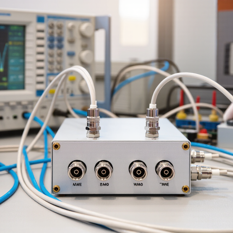
Identify the RF Divider Type and Required Port Configuration
7 Tips for Choosing the Best RF Divider
Identify the RF Divider Type and Required Port Configuration
Start with the signal path, not the catalog label. A two-way Wilkinson divider suits equal, in-phase outputs and provides useful output isolation near its design range. A resistive divider can cover broader frequencies, but its additional loss may weaken low-level signals. A hybrid coupler is different: it splits power with a defined phase relationship and may include an isolated port that needs a termination.
Count the ports carefully. A four-way divider has one input and four outputs; check whether unused outputs require matched loads. For equal splitting, the ideal loss is 3.01 dB per output for two ways and 6.02 dB for four ways. These figures follow the standard RF power-ratio calculation, 10 log10(N), used in microwave network design; real devices add excess insertion loss. Check the frequency range, impedance, connector style, and maximum input power against the actual setup. A 50-ohm system needs a 50-ohm divider. Small mismatches matter.
Phase can matter too. A bench test may look fine with short cables, then drift when cable lengths change. That is easy to overlook. Compare measured insertion loss and port-to-port isolation across the full operating band, not at one convenient frequency. David M. Pozar’s Microwave Engineering discusses Wilkinson dividers, hybrid couplers, and microwave network behavior; use such references to interpret specifications, but verify the selected device with its own test data.
Choosing a divider: Match the output-port count to the number of required signal paths. Ideal equal-split loss is 10·log₁₀(N) dB, where N is the number of outputs; real devices have additional excess insertion loss that varies with design and frequency.
Match the Frequency Range and System Impedance
Check the divider’s full operating band, not just its center frequency. A unit rated from 1 to 2 GHz may behave differently near either edge. Review insertion loss, isolation, and return loss across the frequencies your system actually uses. These figures matter when a weak signal must remain measurable or two output paths need limited interaction. Check the full band.
Impedance must match the rest of the RF chain. Many systems use 50 ohms; some broadcast and cable setups use 75 ohms. Connecting unlike impedances can create reflections, reduce delivered power, and distort measurements. Do not guess. Confirm the divider, cables, connectors, and instruments share the intended impedance. A connector that fits is not proof of an electrical match.
Read the datasheet conditions carefully. Performance may depend on frequency, temperature, and connector type, so a headline specification alone can mislead. For a bench check, use a calibrated vector network analyzer and suitable cables, then measure return loss at the ports across the required band. Even small setup errors can resemble a divider problem. I would still verify the installed assembly, because a tidy specification sheet cannot reveal a loose connector or an unexpected cable mismatch.
Compare Insertion Loss, Amplitude Balance, and Phase Balance
Insertion loss needs careful reading. An equal two-way divider sends half the input power to each output, giving a theoretical split loss of 3.01 dB. The IEEE-published 1960 paper by E. J. Wilkinson describes this equal-Power Divider principle. Compare measured insertion loss against that baseline; the extra loss reflects conductor, dielectric, and mismatch effects. Check the full operating band, not just one attractive center-frequency figure.
Amplitude balance shows how evenly the outputs share power. A 0.5 dB difference may be a useful screening target, but it is not a universal pass limit. Set your tolerance from the system budget. Phase balance matters when outputs feed a combiner or phased array. Even a few degrees of error can disturb the intended signal relationship. Small mismatch, big effect.
Ask for measured S-parameter data across frequency, temperature, and the actual connector configuration. Compare the worst-case amplitude and phase deviations, not only typical values. A neat table can still hide narrow frequency dips. That is easy to miss. If the datasheet omits test conditions, request them before comparing parts; otherwise, the numbers may not describe your setup. I would also verify a sample under the intended cable layout, since routing can shift phase. The data may be imperfect, but documenting that uncertainty is better than treating a single headline value as certainty.
Check Port Isolation, Power Handling, and Connector Compatibility
A divider’s port isolation tells you how well one output is shielded from signals at another. Check the specified isolation across your operating frequency range, not just at one convenient point. Test conditions matter. A calibrated network analyzer and properly terminated ports can reveal differences that a quick continuity check will miss. Strong isolation is useful when outputs feed sensitive receivers, but it cannot compensate for poor impedance matching or faulty cables. Small details matter. Confirm that the specification applies to the divider’s actual configuration and frequency band.
Power handling needs equal scrutiny. Compare the rated average and peak power with your signal’s real duty cycle, including pulsed operation. Leave margin, and check whether the rating changes with temperature or frequency. Uneven output loading can also affect heating; a warm connector deserves investigation, not a guess. Connector compatibility means more than matching thread or gender. Verify the impedance, connector family, mating interface, and frequency rating, then minimize adapters where possible. One overlooked mismatch can cause reflections and reduce delivered power. Specifications may not describe every installation condition, so confirm critical limits with measurements in the intended setup.
Evaluate Environmental Limits, Reliability, and Total Cost
Check the divider’s rated frequency range against the full operating band, not just its center frequency. Then compare its power rating with the highest expected input level. Heat adds stress. Review the specified operating temperature, humidity, and vibration limits, especially for equipment installed outdoors or near warm electronics. A unit that works on a quiet bench may behave differently inside a crowded enclosure.
Reliability depends on more than a rugged case. Look for clear specifications for insertion loss, isolation, amplitude balance, and phase balance across the required band. Check connector type and mounting details, too. Poor cable strain relief or a loose panel fit can create problems long before the divider itself fails. If possible, ask for test data under conditions close to your own. A specification sheet can still leave gaps.
Purchase price is only part of the cost. Consider installation time, calibration needs, replacement access, and the expense of downtime. A lower-cost divider may be sensible for a controlled, low-duty application; it may be a false saving in a hot, hard-to-reach cabinet. Estimate service life carefully. That estimate may be wrong. Leave some margin for temperature and power, but avoid paying for limits your system will never use. The best choice balances verified performance with realistic operating conditions and maintenance needs.
 skip to Main Content
