skip to Main Content

What Is a Reciprocating Compressor and How Does It Work?

A Reciprocating Compressor is a positive-displacement machine that compresses gas inside a cylinder. Its piston moves back and forth, reducing the gas volume during each cycle. This familiar motion appears in refrigeration systems, air tools, natural gas facilities, and process plants. The machine may look simple, but its performance depends on precise timing, sealing, lubrication, and cooling.

During the suction stroke, an inlet valve opens as the piston moves away from the cylinder head. Low-pressure gas enters the chamber. The inlet valve then closes, and the piston reverses direction. Gas pressure rises as the available space becomes smaller. When discharge pressure is reached, the outlet valve opens. Compressed gas flows into the connected pipe.

It is a controlled sequence.

This article explains the main components, operating stages, compressor types, and practical performance factors. Readers will see how pistons, crankshafts, connecting rods, valves, and cylinder heads work together. A technician might hear a sharp valve click, feel vibration through the frame, or notice oil temperature climbing before a failure becomes obvious. These details matter in real maintenance work.

Reliable operation requires more than selecting a stated pressure rating. Engineers must consider gas properties, flow demand, temperature, clearance volume, lubrication, and operating speed. Manufacturer instructions and applicable safety standards should guide installation and servicing. Some explanations simplify compressor behavior, including this one. Actual systems can respond differently under changing loads, poor alignment, or liquid carryover. That uncertainty deserves attention. Understanding those limits helps users evaluate capacity, efficiency, noise, and maintenance requirements with greater confidence.
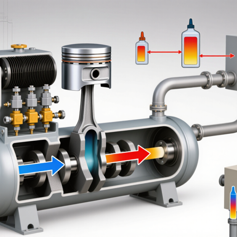
What Is a Reciprocating Compressor and How Does It Work?

What Is a Reciprocating Compressor?

A reciprocating compressor is a positive-displacement machine that uses a piston inside a cylinder.

The piston moves back and forth, driven by a crankshaft and connecting rod. During the suction stroke, the inlet valve opens and draws gas into the cylinder. The valve closes as the piston reverses direction. Gas pressure then rises inside the shrinking space. Finally, the discharge valve opens when internal pressure exceeds the outlet pressure.

This design is common where operators need high pressure, accurate flow control, or intermittent service. Single-stage units suit moderate pressure duties. Multi-stage units compress gas in steps, using intercooling between cylinders.

The U.S. Department of Energy’s Improving Compressed Air System Performance sourcebook reports that compressed-air systems can consume about 10% of industrial electricity. It also notes that leaks may waste 20–30% of compressor output. That makes valve condition and maintenance important. In practice, the textbook cycle is never perfectly clean. Oil carryover, worn rings, heat, and poor alignment reduce efficiency. A 2022 industry energy-efficiency review from the European Commission also emphasizes pressure management and system design as major savings opportunities. The exact result depends on gas type, operating pressure, load pattern, and maintenance quality. A reciprocating compressor is powerful, but not automatically efficient.

Key Components and Their Functions

What Is a Reciprocating Compressor and How Does It Work?

A reciprocating compressor uses a piston to reduce gas volume and raise pressure. The crankshaft converts motor rotation into piston movement. A connecting rod transfers that movement with each stroke. The cylinder provides the compression chamber. Small clearances matter.

During the suction stroke, the inlet valve opens and draws gas inside. The piston then reverses direction. The inlet valve closes, while the discharge valve opens after pressure rises. These valves must seal quickly. Even minor leakage can reduce capacity and increase operating costs.

Piston rings limit gas blow-by along the cylinder wall. Packing seals the piston rod where it leaves the cylinder. Bearings support rotating parts, while the lubrication system reduces friction and removes heat. Intercoolers can lower gas temperature between compression stages. A receiver dampens pulsation and stores compressed gas for changing demand.

The U.S. Department of Energy reports that compressed-air systems may consume about 10% of industrial electricity. Its guidance also identifies leaks as a possible source of 20–30% output loss. These figures vary by plant, pressure, and maintenance quality. Field inspections should therefore include ultrasonic leak checks, valve testing, and oil analysis.

The weakest component matters.

A practical concern is valve wear. It may begin with a faint metallic clicking, then appear as higher discharge temperature or longer running time. The compressor still works, but inefficiently. That imperfect signal deserves investigation, not guesswork.

How the Compression Cycle Works Step by Step

A reciprocating compressor traps gas inside a cylinder and reduces its volume with a moving piston.

The cycle begins during suction. As the crankshaft pulls the piston back, cylinder pressure falls below inlet pressure. The suction valve opens, and gas fills the space. At the end of this stroke, the valve closes. Small timing errors matter.

Compression starts when the piston moves inward. Both valves remain closed, so the trapped gas occupies less volume and its pressure rises. Temperature rises too, which technicians can feel near the discharge line after steady operation.

When cylinder pressure exceeds discharge pressure, the discharge valve opens. Compressed gas leaves through the outlet, often producing a sharp mechanical pulse. The piston then reverses direction, and the cycle repeats.

A small clearance volume remains above the piston. Gas trapped there expands during the next return stroke, delaying fresh intake. This reduces actual capacity, even when the cylinder’s theoretical displacement looks impressive.

The U.S. Department of Energy’s Improving Compressed Air System Performance sourcebook reports that compressed air may account for roughly 10% of industrial electricity use, depending on the facility.

That figure explains why valve leakage, high discharge pressure, and poor cooling deserve attention. Industry efficiency assessments also show that operating conditions can change substantially across a shift.

In practice, a clean filter and correct lubrication may matter more than a perfect calculation. Engineers should verify pressure, temperature, vibration, and flow on site. Theory helps, but machines remain slightly untidy.

Types of Reciprocating Compressors

What Is a Reciprocating Compressor and How Does It Work?

A reciprocating compressor uses a piston to compress gas inside a cylinder. The crankshaft drives the piston through repeated movement. Suction valves admit gas, while discharge valves release it at higher pressure. The design is simple, but valve timing matters greatly.

Types of Reciprocating Compressors

Single-acting and double-acting compressors Single-acting compressors compress gas on one piston side. They suit smaller duties and intermittent operation. Double-acting compressors use both piston sides, increasing capacity within a similar frame size.

Single-stage and multistage models Single-stage models compress gas once, while multistage units divide compression across several cylinders. Intercoolers reduce temperature between stages. This matters when pressure ratios become demanding.

Lubricated and oil-free compressors Lubricated compressors use oil to reduce friction and seal piston rings. Oil-free models avoid oil contact with the compressed gas. They often require tighter manufacturing tolerances and stronger maintenance discipline.

Diaphragm compressors Diaphragm compressors use a flexible membrane instead of direct piston contact. They support applications needing very clean gas.

The U.S. Department of Energy’s Improving Compressed Air System Performance guide reports that compressed-air systems may consume 10–15% of a manufacturing plant’s electricity. That figure makes efficiency more than a technical preference.

Piston speed, clearance volume, leakage, and cooling conditions all affect real performance. Laboratory ratings can look excellent. Field results may disagree.

A neglected valve can quietly erase expected savings. Reliable selection requires pressure, flow, gas composition, duty cycle, and service records—not pressure alone.

Applications, Benefits, and Operating Limitations

A reciprocating compressor uses a piston moving inside a cylinder to compress gas. As the piston moves back, the inlet valve opens and draws gas into the chamber. The piston then moves forward, raising pressure before the discharge valve releases the gas. This repeated motion delivers high pressure at relatively low flow rates. In field inspections, vibration, oil condition, and valve temperature often reveal problems before failure becomes obvious.

These compressors serve refrigeration systems, gas storage, pneumatic tools, and process equipment. They are especially useful when applications require strong pressure performance and accurate capacity control. Their compact cylinders can handle demanding pressure ratios, while unloading systems can reduce output during lighter demand. The result is practical. However, the equipment produces pulsation, noise, and mechanical vibration. Proper foundations, flexible connections, and pulsation dampers can reduce these effects.

Operating limitations deserve equal attention. Piston rings, valves, bearings, and packing require regular inspection because each part experiences repeated loading. Excessive discharge temperature may damage lubricants or weaken components. Liquid entering the cylinder can cause severe mechanical damage, so suction separators and careful system control are essential. Reciprocating compressors also respond poorly to frequent starts and stops. Their efficiency can fall when flow demand changes rapidly. In my experience, selecting capacity only from peak pressure is a common mistake; gas composition, duty cycle, cooling conditions, and maintenance access matter just as much. No design is perfect. Trade-offs remain.

What Is a Reciprocating Compressor and How Does It Work?

Applications, Benefits, and Operating Limitations

Reciprocating compressors use a piston moving inside a cylinder to draw in, compress, and discharge gas through suction and discharge valves. The representative pressure levels below show common application ranges rather than fixed equipment limits.

Key Benefits

High pressure capability, strong efficiency at part load, and good suitability for low-to-medium flow applications.

Operating Limitations

Pulsating flow, vibration, valve and ring wear, noise, and a higher maintenance requirement than many rotary designs.

Back To Top
