skip to Main Content

How to Choose a Thermal Expansion Vessel?

Choosing the right Thermal Expansion Vessel is essential for stable, safe, and efficient heating or water systems. When water heats, it expands. Without enough room for that expansion, pressure can rise quickly, causing dripping relief valves, noisy pipes, or premature component failure. A correctly selected vessel helps absorb this pressure change and protects the system during daily operation.

The decision involves more than matching pipe size. You need to examine the system volume, operating temperature, maximum working pressure, static height, and expected pressure range. For example, a small domestic heating circuit may require a compact vessel, while a larger commercial installation needs greater capacity and stronger materials. The vessel’s diaphragm or bladder must also suit the fluid and temperature conditions. Check the manufacturer’s technical data carefully.

Small details matter.

In practice, installers should measure actual conditions instead of relying only on assumptions. Pre-charge pressure must be checked with the vessel isolated and depressurized, using a reliable gauge. Incorrect settings can make a suitable vessel perform poorly. I have seen pressure problems blamed on undersized equipment when the real issue was an incorrect pre-charge or blocked connection. That possibility deserves attention.

Material quality, certification, maintenance access, and replacement availability also influence the choice. An experienced professional will compare calculations with site conditions and allow reasonable safety margins. No selection method is perfect. Systems change over time, and old assumptions may become unreliable. This guide explains the key factors clearly, helping readers choose a Thermal Expansion Vessel with greater confidence and fewer costly surprises.

How to Choose a Thermal Expansion Vessel?

What Is a Thermal Expansion Vessel and Why Is It Needed?

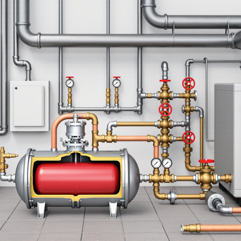
A thermal expansion vessel is a sealed tank connected to a pressurized water system. It contains water on one side and compressed air or nitrogen behind a flexible membrane. When water heats, it expands. Because water cannot compress easily, system pressure rises. The vessel absorbs this extra volume and helps prevent leaking joints, noisy pipes, or frequent relief-valve discharge. In a heating system, you may notice its value when a pressure gauge stays steady during repeated heating cycles.

Choosing the right vessel requires more than matching pipe size. Check the system’s water volume, maximum temperature, working pressure, and required pre-charge pressure. A qualified installer should also confirm the connection position and local installation requirements. For domestic water systems, use a vessel designed for potable water. For heating circuits, select materials suitable for the system fluid. An oversized vessel may cost more, while an undersized one can leave pressure unstable. Field conditions can challenge neat calculations.

Tips: Check the vessel’s air pressure when the system is cool and isolated. A flat pressure reading may indicate a damaged membrane, not a simple adjustment issue. Inspect the pressure gauge during a complete heating cycle. Keep service records with the installation date, pressure readings, and inspection notes. Do not rely on appearance alone; a vessel can look sound while its internal membrane has failed.

How to Identify the Required Vessel Type and System Application

How to Choose a Thermal Expansion Vessel?

The required vessel type depends on the fluid, temperature range, and system layout. A closed-loop heating system usually needs a diaphragm or bladder vessel. It absorbs water expansion as temperature rises. A potable water system requires a vessel approved for drinking-water contact. Solar thermal systems need higher temperature resistance and compatibility with glycol mixtures. Do not select by pipe size alone.

ASHRAE Handbook—Fundamentals provides water-density data for expansion calculations. Water heated from about 10°C to 90°C expands by roughly 3.5%. A 500-litre system may therefore gain nearly 18 litres of volume. The vessel must accept this increase while maintaining safe operating pressure. Check the minimum cold pressure, maximum working pressure, relief-valve setting, and vessel pre-charge. The 2024 ASHRAE guidance also stresses accurate fluid-property data for hydronic design. Small errors can matter.

Tips: Record the actual system volume, not only the boiler rating. Include pipes, heat emitters, collectors, and heat exchangers. For glycol systems, use the manufacturer’s density and expansion data. Confirm membrane compatibility. Installation experience shows that incorrect pre-charge is common. It can cause pressure swings, noise, or frequent relief-valve discharge. A perfect selection is not always possible from a catalogue. When system records are incomplete, measure carefully and have a qualified engineer verify the final sizing.

How to Choose a Thermal Expansion Vessel? - How to Identify the Required Vessel Type and System Application

System Application System Fluid Why Expansion Control Is Needed Recommended Vessel Type Membrane or Bladder Requirement Typical Operating Temperature Key Sizing Inputs Important Selection and Installation Notes
Closed Hydronic Heating Water or water–glycol mixture Fluid volume increases as the heating system temperature rises, causing pressure to increase in a sealed circuit. Use a membrane compatible with the system fluid and operating temperature. For glycol mixtures, verify chemical compatibility. Approximately 60–90°C in many building heating systems; the actual design temperature depends on the heat source and controls. System water volume, minimum and maximum operating temperatures, static system height, cold fill pressure, safety-valve setting, and glycol concentration. Install on the suction side of the circulation pump where possible. The vessel pre-charge must be set with the water side isolated and depressurized, according to the system design.
Domestic Hot Water Potable water Heating water in a closed or check-valve-protected supply expands and can raise pressure when backflow is prevented. Use a certified potable-water diaphragm or bladder made from materials approved for drinking-water contact in the applicable market. Usually approximately 50–60°C at the storage or distribution system, subject to local hygiene and safety requirements. Water-heater volume, cold-water temperature, hot-water setpoint, incoming pressure, pressure-reducing valve setting, and allowable maximum pressure. Do not use a heating-only vessel in a potable-water system. Install downstream of a check valve or pressure-reducing valve and upstream of the water heater where the system design requires it.
Solar Thermal Heating Water–glycol solar fluid or water, depending on system design Solar collectors can reach high stagnation temperatures, producing significant fluid expansion and possible vapor formation. Membrane must tolerate the specified solar fluid, elevated temperature, and repeated thermal cycling. A separate cooling or intermediate vessel may be required. Normal operation may be approximately 70–120°C; stagnation temperatures can be substantially higher depending on collector design. Collector and pipe volume, fluid expansion coefficient, minimum and maximum temperatures, static height, system pressure limits, vapor reserve, and safety-valve setting. Confirm the vessel temperature rating and glycol compatibility. Protect the vessel from excessive collector heat when required by the system manufacturer or design standard.
Closed Chilled-Water System Chilled water or water–glycol mixture Pressure changes occur because of fluid temperature variation, system filling, and changes in system volume in a closed circuit. Use a membrane compatible with glycol concentration and low-temperature operation. Select insulation or vapor protection where condensation may occur. Commonly approximately 5–15°C, with the exact range determined by the cooling equipment and design conditions. System volume, fluid concentration, minimum and maximum temperatures, static height, fill pressure, operating pressure, and relief-valve setting. Install and insulate the vessel to prevent surface condensation. The connection point should be selected to maintain stable pressure throughout the chilled-water circuit.
Boiler Primary Circuit Water or water–glycol mixture Heat input in the boiler circuit increases fluid temperature and volume while the circuit remains closed. Verify temperature, pressure, and fluid compatibility with the boiler circuit and any corrosion-inhibitor or glycol additive. Often approximately 70–100°C, although the maximum design temperature may be higher depending on the boiler type. Primary-loop volume, boiler operating temperature, cold fill pressure, system height, maximum working pressure, and safety-valve setting. Do not size only from boiler output. Include the boiler, connected pipework, heat exchangers, and any buffer or low-loss header volume.
Buffer Tank or Thermal Storage System Water or water–glycol mixture Large stored-water volume creates a substantial expansion volume as the tank cycles between its minimum and maximum temperatures. Membrane compatibility must match the fluid, maximum temperature, and expected number of thermal cycles. Commonly approximately 30–95°C, depending on whether the tank serves heating, renewable-energy, or heat-recovery equipment. Total stored and connected water volume, minimum and maximum tank temperatures, static height, pressure limits, and available installation space. Include the full tank volume in the calculation. Check connection size, vessel acceptance volume, and whether multiple vessels require balanced connection arrangements.
Pressure-Boosting or Domestic Water Supply Potable cold water The vessel reduces pump cycling and absorbs small pressure or flow fluctuations in a pressurized water-supply system. Use drinking-water-approved materials and a membrane designed for frequent cycling and the specified pressure range. Normally close to the incoming cold-water temperature, commonly approximately 5–25°C depending on location. Pump flow rate, pump start and stop pressures, required drawdown, expected demand cycles, inlet pressure, and maximum working pressure. Set pre-charge in relation to the pump control pressures. The vessel is primarily for pressure stabilization and drawdown, not for absorbing heating-system expansion unless specifically designed for that purpose.
Fire-Protection or Sprinkler Water System Water, subject to the system design Small temperature-related volume changes and pressure maintenance requirements can affect supervisory pressure in a closed fire-protection pipe network. Material and construction must comply with the governing fire-protection requirements and local authority approvals. Usually near ambient temperature, but the design must account for the full expected environmental temperature range. Trapped system volume, ambient temperature range, pressure-maintenance arrangement, maximum allowable pressure, and applicable fire-protection rules. Do not substitute a general-purpose heating or potable-water vessel without confirming approval and compatibility with the fire-protection design.
Process or Industrial Closed Loop Water, glycol solution, heat-transfer fluid, or another approved process liquid Thermal expansion, pressure fluctuation, and fluid contraction can affect equipment integrity and process stability. Confirm membrane, coating, and elastomer compatibility with the chemical composition, concentration, temperature, and cycle frequency. Application-specific; the complete minimum and maximum temperature range must be used for selection. Fluid density and expansion coefficient, system volume, temperature range, operating pressure, design pressure, allowable pressure variation, and safety-device settings. Use the fluid manufacturer’s data for expansion properties. Check material compatibility, fatigue life, certification, corrosion allowance, and maintenance access before final selection.
Vessel selection should be confirmed against the equipment manufacturer’s data, local regulations, applicable pressure-equipment requirements, and the complete system pressure-temperature design.

How to Calculate the Correct Vessel Capacity

How to Choose a Thermal Expansion Vessel?

How to Calculate the Correct Vessel Capacity

Correct sizing starts with the total water volume, not only the boiler or heat exchanger. Include radiators, pipes, storage tanks, valves, and any hidden loops. A small omission can change the result.

Estimate the water expansion between the cold filling temperature and the highest operating temperature. For example, 300 litres of water heated from 10°C to 80°C may expand by approximately 2.9%, producing 8.7 litres of expansion. Use reliable water-property data when temperatures are high. Guesswork is convenient, but it can be expensive.

The vessel’s nominal capacity must exceed its usable acceptance volume. A practical calculation uses: vessel volume = expansion volume × (maximum absolute pressure) ÷ (maximum pressure minus pre-charge pressure) With 8.7 litres of expansion, a 3 bar maximum pressure, and a 1.5 bar pre-charge, the result is about 23.2 litres. Select the next suitable size, then allow a sensible margin for measurement errors and future changes. Check whether the stated pre-charge is gauge or absolute pressure. This detail is often overlooked. Verify the air pressure with the vessel isolated and empty of system pressure. Also confirm the relief valve setting, minimum fill pressure, temperature rating, and connection position. A final pressure check during commissioning may reveal assumptions that looked correct on paper.

How to Check Pressure, Temperature, and Material Compatibility

Choosing a thermal expansion vessel starts with three checks: pressure, temperature, and material compatibility. In practical commissioning, measure the system cold, not only from the gauge after heating. Record static pressure, fill pressure, relief-valve setting, and operating temperature. A vessel pre-charge set too high may accept almost no water. Set too low, and the diaphragm can work unnecessarily hard.

Temperature changes volume. IAPWS water-property data shows that water expands by roughly 3% between 10°C and 80°C. That change needs room inside the vessel. Use the actual fluid temperature, not a convenient estimate. EN 12828 guidance also links vessel selection with system pressure, safety limits, and usable expansion volume. Check the vessel’s maximum working temperature, diaphragm rating, and connection temperature. A boiler’s maximum setting is not always the vessel’s real operating condition.

Material compatibility is easier to overlook. Confirm the fluid type, glycol percentage, pH, oxygen exposure, and possible chloride content. Water-glycol mixtures expand differently from treated water, and their viscosity can alter charging and circulation behavior. Chemical compatibility tables from the vessel supplier and maintenance data should support the decision. Never rely on appearance alone. A diaphragm may look fine while aging has reduced flexibility. I have seen pressure readings change after air removal, so recheck after commissioning. Small mistakes matter. Cite: IAPWS Industrial Formulation 1997; EN 12828:2012+A1:2014; ASHRAE Handbook—HVAC Systems and Equipment, 2024.

How to Choose a Thermal Expansion Vessel

How to Check Pressure, Temperature, and Material Compatibility

The chart shows the approximate volumetric expansion of water compared with its volume at 10°C. As temperature rises, the expansion vessel must provide enough acceptance volume to control the resulting pressure increase.

Pressure Check
Set the vessel pre-charge according to the system’s cold-fill pressure and static head. Confirm that the vessel and relief valve ratings exceed the maximum operating pressure.
Temperature Check
Select a vessel with a temperature rating suitable for the lowest and highest operating temperatures, including possible short-term peaks.
Material Compatibility
Check the membrane material, vessel lining, and connections against the fluid. Potable water, glycol mixtures, heating water, and corrosive fluids may require different materials.

Expansion values are approximate and calculated from standard water-density data relative to 10°C. Actual vessel sizing also depends on system volume, pressure limits, fluid composition, and operating conditions.

How to Install, Set Up, and Maintain the Vessel Safely

How to Choose a Thermal Expansion Vessel?

A thermal expansion vessel should match the system fluid, temperature range, working pressure, and total water volume. For a heating circuit, estimate the water content from pipes, radiators, and the heat source. Then allow for expansion between the cold and operating temperatures. A vessel that is too small may trigger the safety valve repeatedly. An oversized vessel usually costs more and may respond poorly if its pressure is set incorrectly.

Installation quality matters just as much as vessel size. Mount the vessel on the cooler return pipe, close to the expansion connection, unless the system design states otherwise. Keep the connection short and unobstructed. The vessel must never be isolated from the safety valve by a closed valve.

Before filling, check the diaphragm pre-charge with the water side depressurised. Set it according to the system’s cold filling pressure and the manufacturer’s data. Use a calibrated gauge.

Small details matter. Keep the vessel supported. Protect it from freezing, vibration, and excessive heat. After filling, inspect every joint while the pump runs and stops. Watch the pressure gauge through a complete heating cycle.

A stable reading is reassuring, but not proof of perfect sizing. I have found that real pipe volume is often underestimated. Record the initial pressure, operating temperature, and inspection date.

Check for corrosion, leaks, damaged threads, and abnormal pressure changes at least annually. Replace a vessel when its diaphragm fails; do not attempt an improvised repair.

Back To Top